English

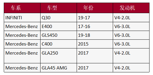
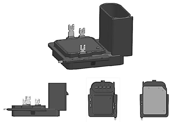
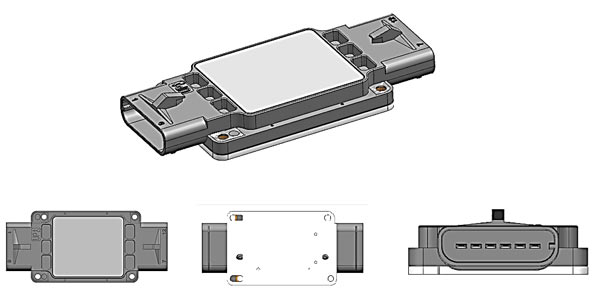
JK-M143 Series
Features
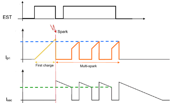
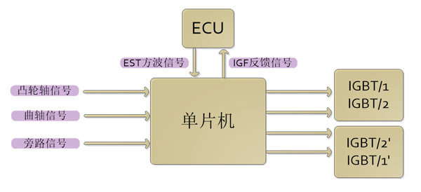
1, multiple ignition function
2. Primary and secondary current detection
3. Primary current feedback
4. Primary current limit shutdown protection
5. Multiple ignition time protection
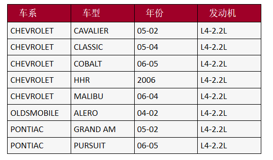
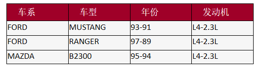
Application model
JK-M153A-001
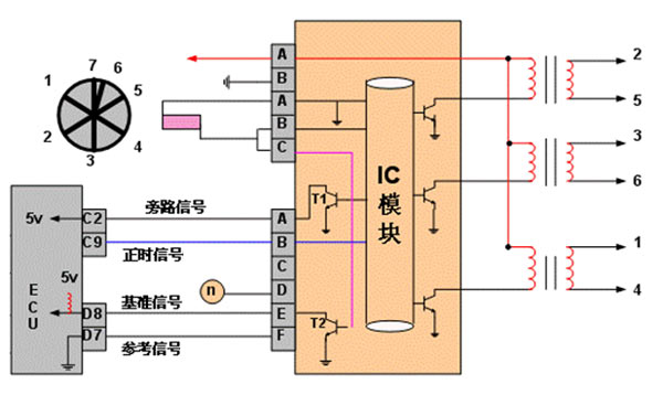
Features
1, judging cylinder
2, ignition timing allocation
3. Speed ??signal output
4. Closed corner adjustment
5. Dual working mode switching
Application model
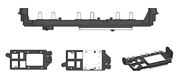
JK-M155A-001
Features
1, secondary ignition signal induction
2. Judging cylinder signal output
3. Ignition timing assignment
4. Time protection
Application model
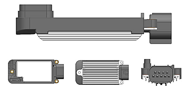

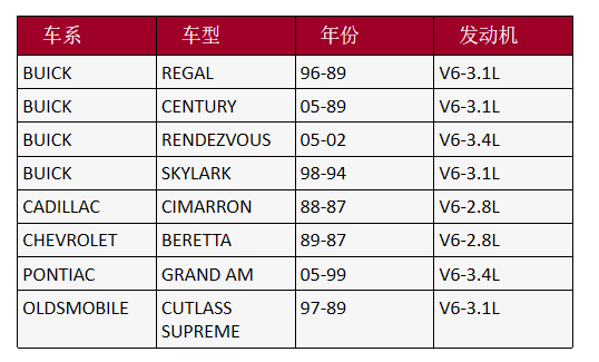
JK-M157A-001
Features
1, judging cylinder
2, ignition timing allocation
3, ignition signal feedback
4. Dual working mode switching
Application model
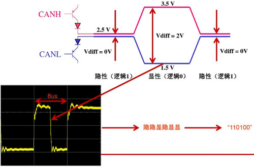
Controller Area Network CAN (Controller Area Network), originally designed by the German BOSCH company, is used for gas monitoring and control.
In September 1991, Philips Semiconductors formulated and released the CAN technical specification: CAN 2.0A/B. In November 1993, the ISO organization officially promulgated the CAN international standard ISO11898.
Nominal value of CAN bus level
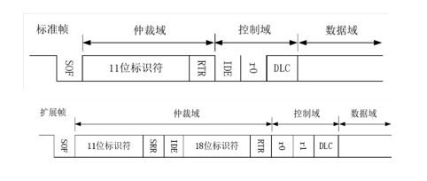
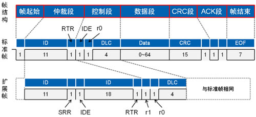
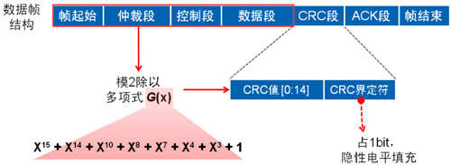
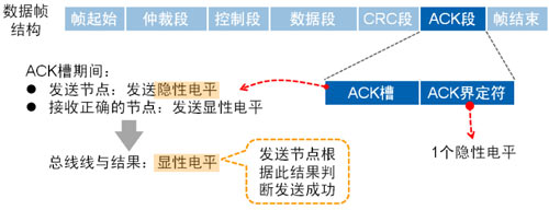
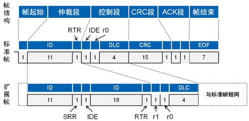
data frame
Structured by 7 segments, frame start, arbitration segment, control segment, data segment, CRC segment, ACK segment and end of frame (VBUS /2) Compare. The figure below shows the circuit used to implement this method.
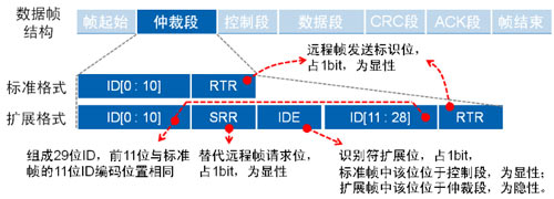
Remote Frame
Compared with the data frame, there is no data segment on the remote frame structure, which is composed of 6 segments, the same The standard frame format and the extended frame format are divided, and the RTR bit is 1 (recessive level).
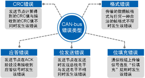
Error frame
Despite the high reliability of CAN communication, errors may still occur. There are five types of errors.
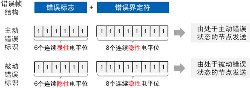
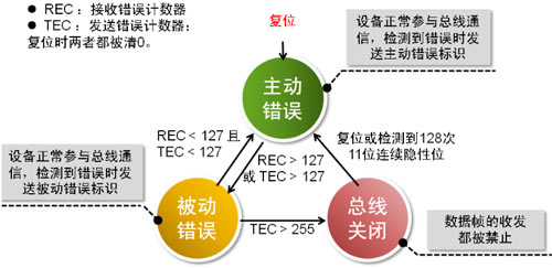
In order to prevent itself from being unable to receive the normal amount due to some reasons, the node always sends error frames and interferes with the communication of other nodes. CAN BUS stipulates three types of nodes State and its behavior.
Overload frame
When a receiving point is not ready to accept the next frame of data, it will send an overload frame to notify the sending node. The overload frame consists of the overload flag and Composed of overload delimiters.
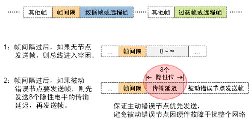
Frame interval
The frame interval is used to separate the data frame or remote frame from the frame between them, However, the frame interval will not be inserted in the front door of overloaded frames and erroneous frames.
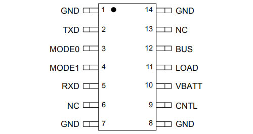
CAN BUS IC typical classification and representative
High-speed CAN: TJA1042T
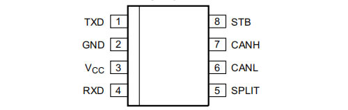
Low speed/fault-tolerant CAN: TJA1054T
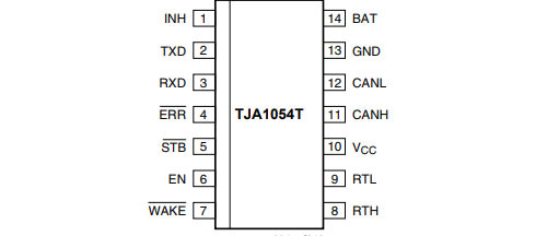
Low speed/fault-tolerant CAN: TJA1054T
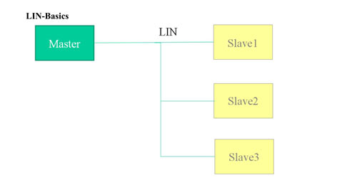
LIN Bus
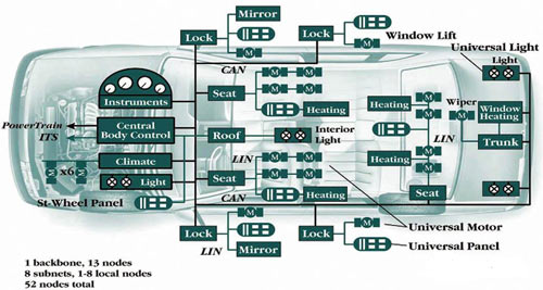
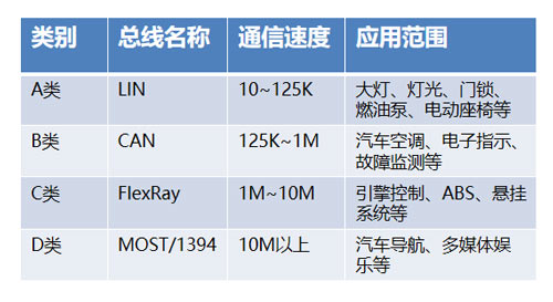
Four major automotive communication protocols: LIN, CAN, FlexRay, MOST
LIN bus is a low-cost, low-speed serial communication network defined for automotive distributed electronic systems. CAN) a supplement. The LIN bus is based on the SCI (UART) data format and uses a single master controller/multiple slave device mode, which is a special case in UART
The characteristics and structure of LIN bus
Single bus (+GND and Vbat)
Master/Slave concept
There is only one master node and multiple slave nodes
The master node controls the bus
Bus speed 9600...1920Bit/s
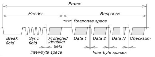
Transmitting data frames on the LIN bus is the smallest unit consisting of the following elements:
discontinuity, synchronization, frame identifier, data bytes (1...8) and checksum
Intermittent, synchronous, frame identifier (Header) is always transmitted by the master node
Data bytes are provided by the master node or a slave node, depending on whether the master node and the slave node are the publishers of the frames
The frame node task is defined in the LIN description file (LDF), and each frame (frame identifier) ??is designated as a publisher’s Node
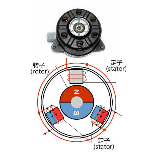
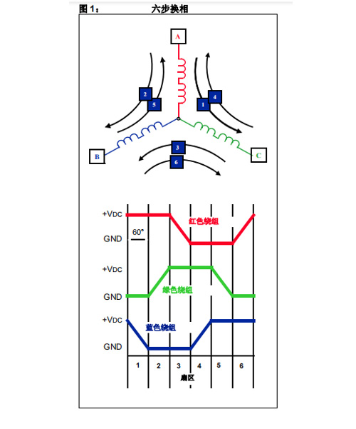
BLDC square wave control
BLDC motor is traditionally defined as a permanent magnet synchronous motor with trapezoidal back-EMF waveform shape.
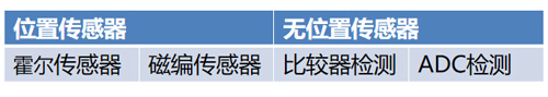
Because electrical excitation must be synchronized with the rotor position, BLDC motors usually require one or more rotor position sensors when running. For reasons of cost and reliability, the motor is suitable for operation without a position sensor, which is commonly referred to as sensorless operation. By detecting the BEMF voltage on the non-energized phase winding, the commutation time of the motor drive voltage can be determined.
Advantages of the sensorless algorithm:
1. Save device cost and installation cost.
2. Improve the stability, the position sensor chip is easily damaged under high temperature and high humidity commutation. Therefore, Jianke Electronics launched the sensorless control technology, which solves the above problems well.
Two algorithms for BLDC sensorless control
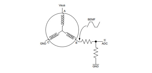
Zero crossing detection method
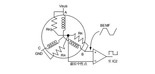
BEMF voltage is compared with half of the DC bus voltage. This method is based on the assumption that a zero-crossing event occurs when the BEMF voltage is equal to VDC/2. The comparator compares the BEMF voltage with half of the DC bus voltage (VBUS/2). The figure below shows the circuit used to implement this method.
Advantages: small amount of calculation, can achieve high speed
Disadvantages: not flexible enough.
Voltage comparison method
It can be simplified by using a variable threshold voltage point to detect zero crossing events. This variable voltage is the neutral point of the motor. The neutral point of most BLDC motors will not be led out with wires. But the neutral point can be constructed with a resistance network. Connect one end of the three resistors in parallel with the three-phase winding of the motor, and connect the other end together to create a virtual neutral point, as shown in the figure below.
Advantages: The algorithm is flexible and can be quickly started.
Disadvantages: large amount of calculation and complicated algorithm.
The advantages of Jianke Electronic’s BLDC square wave control solution without position sensor:
1. Wider speed adjustment range.
In the traditional control algorithm, only one upper bridge and one lower bridge are connected at a time. Jianke Electronics has optimized the algorithm. On the basis of two or two connections, three or three connections are added to increase the conduction angle. Increase the speed.
Disadvantages: large amount of calculation and complicated algorithm.
2. Faster startup performance.
The fast start algorithm of Jianke Electronics has been applied to the fuel pump, which can ensure that it starts to the highest speed within 150ms.
3. High robustness.
Jianke Electronics uses the MCU comparator to detect the BEMF of the motor, while reducing costs, it can implement more complex software algorithms, thereby improving robustness.
Phone: +86 731-88081666(IDD)
Fax: 0731-88081666
Email: sales@jkaec.com
Address: Wangcheng Economic and Technological Development Zone, Changsha
10 Hangkong Road
Phone: +86 755-25214880(IDD)
Fax: 0755-25227666
Email: sales@ignition-module.com
Address: Building 3, Beishan Industrial Zone, Beishan Road, Yantian District, Shenzhen


Phone: 0755-25214880
Fax: 0755-25227666
Email: sales@ignition-module.com
Address: Building 3, Beishan Industrial Zone, Beishan Road, Yantian District, Shenzhen
