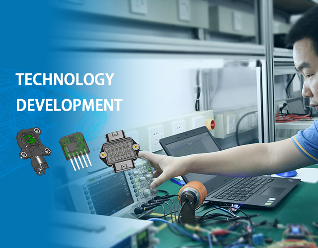
In the field of ignition modules, Jianke Electronics basically includes products corresponding to all vehicle models worldwide, including many complex ignition systems such as multiple ignition functions, ignition modules with cylinder detection functions, ion flow detection modules, and so on.
Jianke's micro motor controller covers all control methods of motor control, including FOC, SVPWM, and square wave. Jianke has rich experience in CAN protocol, LIN protocol, BSD protocol, SPI protocol, and other mature products in micro motor controllers, sensors, and other automotive electronic products.
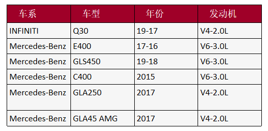
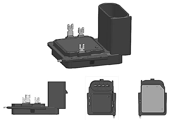
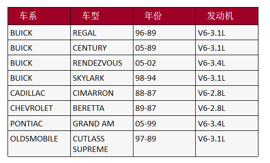
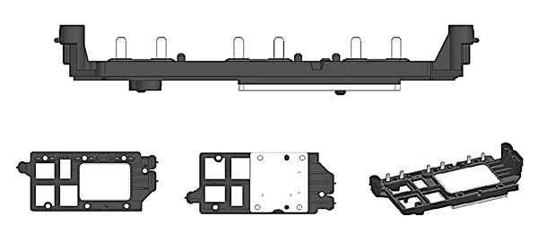
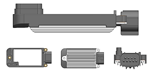
JK-M143 Series
Functional features
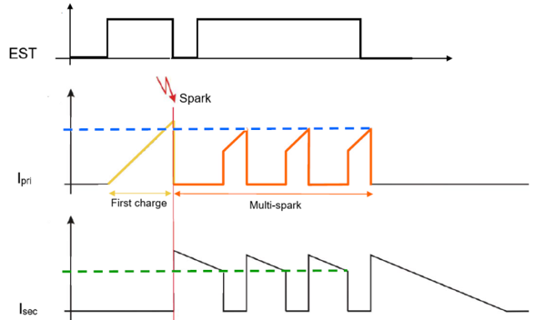
1. Multiple ignition function
2. First level current detection
3. Primary current feedback
4. Primary current limiting shutdown protection
5. Multiple ignition time protection
Application model
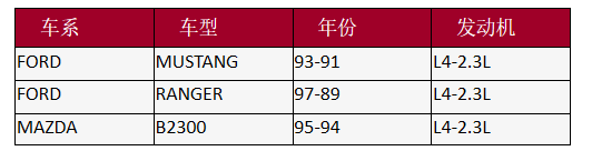
JK-M153A-001
Functional features
1. Judging cylinder
2. Ignition timing allocation
3. Speed signal output
4. Closing angle adjustment
5. Dual working mode switching
Application model
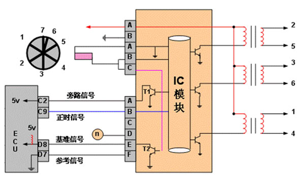
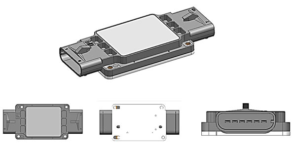
JK-M155A-001
Functional features
1. Secondary ignition signal induction
2. Cylinder detection signal output
3. Ignition timing allocation
4. Time protection
Application model
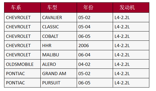

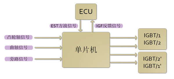
JK-M157A-001
Functional features
1. Judging cylinder
2. Ignition timing allocation
3. Ignition signal feedback
4. Dual working mode switching
Application model
Controller Area Network (CAN), originally designed by BOSCH in Germany, is used for gas monitoring and control.
In September 1991, Philips Semiconductor Company developed and released the CAN technical specification: CAN 2.0A/B. In November 1993, ISO officially issued the CAN international standard ISO11898.
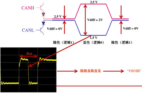
CAN bus level nominal value
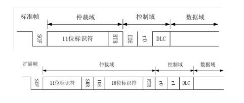
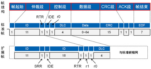
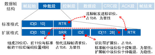
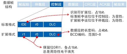
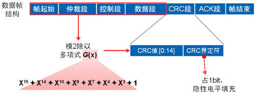
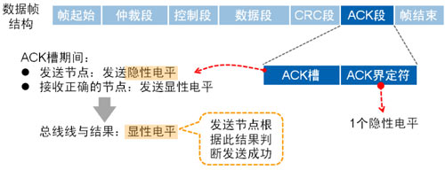
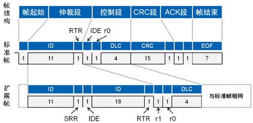
Data frame
Structurally, it consists of 7 segments, including frame start, arbitration, control, data, CRC, ACK, and frame end (VBUS/2) for comparison. The diagram below shows the circuit used to implement this method.
Remote frame
Compared to data frames, remote frames have no data segments in structure and are composed of 6 segments
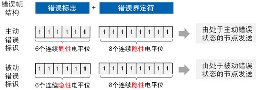
Error frame
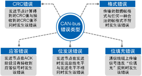
Despite the high reliability of CAN communication, errors may still occur. There are five types of errors.
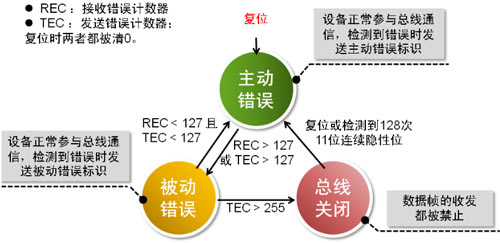
To prevent the node from continuously sending incorrect frames and interfering with communication with other nodes due to certain reasons, CAN BUS specifies three states and behaviors of the node.
Overload frame
When a receiving point is not ready to receive the next frame of data, an overloaded frame will be sent to notify the sending node. The overloaded frame consists of an overload flag and an overload delimiter.
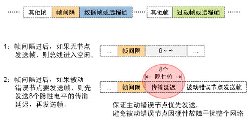
Frame interval
Frame spacing is used to separate data frames or remote frames from the frames between them,
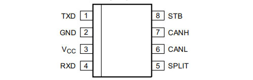
Typical Classification and Representative of CAN BUS ICs
High speed CAN: TJA1042T
Low speed/fault-tolerant CAN: TJA1054T
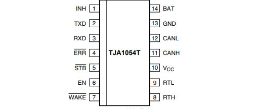
Low speed/fault-tolerant CAN: TJA1054T
LIN Bus
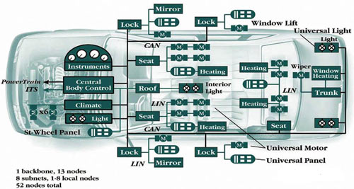
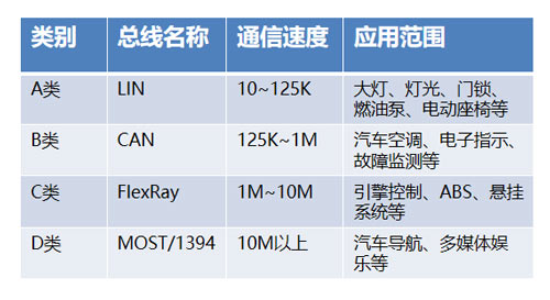
The four major communication protocols for automobiles:
LIN bus is a low-cost, low-speed serial communication network defined for automotive distributed electronic systems, and is a supplement to Controller Area Network (CAN). The LIN bus is based on the SCI (UART) data format and adopts a single master controller/multiple slave device mode, which is a special case in UART
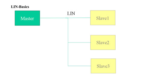
The characteristics and structure of LIN bus
Single bus (+GND and Vbat)
Master/Slave Concept
Only one master node, multiple slave nodes
The master node controls the bus
Bus speed 9600... 1920Bit/s
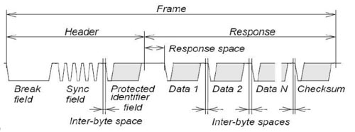
Transferring data frames on the LIN bus is the smallest unit composed of the following elements:
Interruption, synchronization, frame identifier, data bytes (1... 8), and checksum
Intermittent, synchronous, and frame identifier (header) always rely on the master node for transmission
The data bytes are provided by the master node or a slave node, depending on whether the master and slave nodes are the publishers of the frame
The node task of a frame is defined in the LIN description file (LDF), and each frame (frame identifier) is designated as a publisher's node
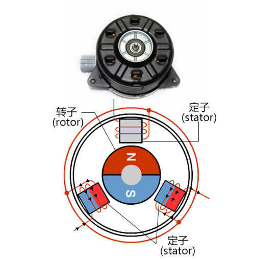
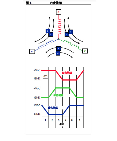
BLDC square wave control
BLDC motor is traditionally defined as a permanent magnet synchronous motor with a trapezoidal back electromotive force waveform shape.
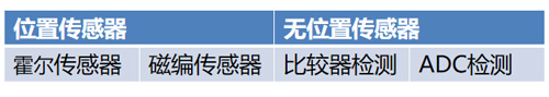
Due to the requirement of synchronous excitation with rotor position, BLDC motors typically require one or more rotor position sensors during operation. Due to cost and reliability reasons, motors are suitable for operation without position sensors, commonly known as sensorless operation. The commutation time of the motor drive voltage can be determined by detecting the BEMF voltage on the non electric phase winding.
Advantages of position sensorless algorithm:
1. Save device and installation costs.
2. Improve stability, position sensor chips are prone to damage under high temperature and high humidity commutation. So Jianke Electronics has launched sensorless control technology, which effectively solves the above problems.
Two algorithms for BLDC sensorless control
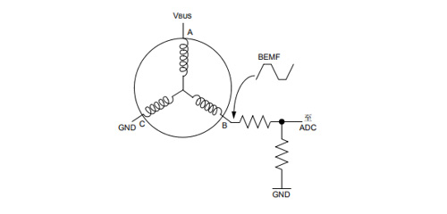
Zero crossing detection method
The method of comparing the BEMF voltage with half of the DC bus voltage is to use a comparator to compare the BEMF voltage with half of the DC bus voltage (VBUS/2), assuming a zero crossing event occurs when the BEMF voltage is equal to VDC/2. The diagram below shows the circuit used to implement this method.
Advantages: Low computational complexity, capable of achieving high rotational speeds
Disadvantage: Not flexible enough.
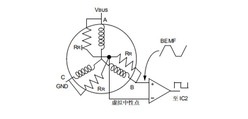
Voltage comparison method
It can be simplified by using variable threshold voltage points to detect zero crossing events. The variable voltage is the neutral point of the motor. The neutral point of most BLDC motors is not led out by wires. But a resistance network can be used to construct the neutral point. Connect one end of the three resistors in parallel with the three-phase winding of the motor, and the other end together to create a virtual neutral point, as shown in the following figure.
Advantages: The algorithm is flexible and versatile, and can achieve fast startup.
Disadvantages: Large computational load and complex algorithm.
Advantages of the BLDC square wave control scheme without position sensors by Jianke Electronics:
1. Wider speed regulation range.
The traditional control algorithm only has one upper bridge and one lower bridge conducting at a certain moment. Jianke Electronics has optimized the algorithm and added three to three conducting on the basis of pairwise conducting, increasing the conducting angle and thus increasing the speed.
Disadvantages: Large computational load and complex algorithm.
2. Faster startup performance.
The fast start algorithm of Jianke Electronics has been applied to the fuel pump, ensuring that it can start to the maximum speed within 150ms.
3. High robustness.
Jianke Electronics uses MCU comparators to detect motor BEMF, reducing costs while implementing more complex software algorithms, thereby improving robustness.
Phone: +86 731-88081666(IDD)
Fax: 0731-88081666
Email: sales@jkaec.com
Address: Wangcheng Economic and Technological Development Zone, Changsha
10 Hangkong Road
Copyright © 长沙市健科电子有限公司粤ICP备19004628号粤ICP备19004628号
长沙市健科电子有限公司 深圳市健科电子有限公司 Website Map
Internet brand service:CTMON